Due to poor wifi reception I decided to change from the NodeMCU to a WEMOS DI Mini Pro MCU with external antennae. I flashed the MCU and plugged in the sensors.
The PM sensor works fine.
The BME280 is NOT sending data.
I took a second WEMOS MCU and tested the BME280 board alone using Adafruits BME280 test code and the sensor works on pins D1/D2 and also on D5/D7 but NOT on D3/D4.
This eliminates the BME280 and points to an issue with the WEMOS MCU and I2C on pins D3/D4.
Can this really be possible or have I missed something?
Wemos D1 mini pro works with BME280 without any problems on D3/D4 pins. We use hundereds of them.
Could your please provide photos how you connected your setup?
Thank you for your prompt response.
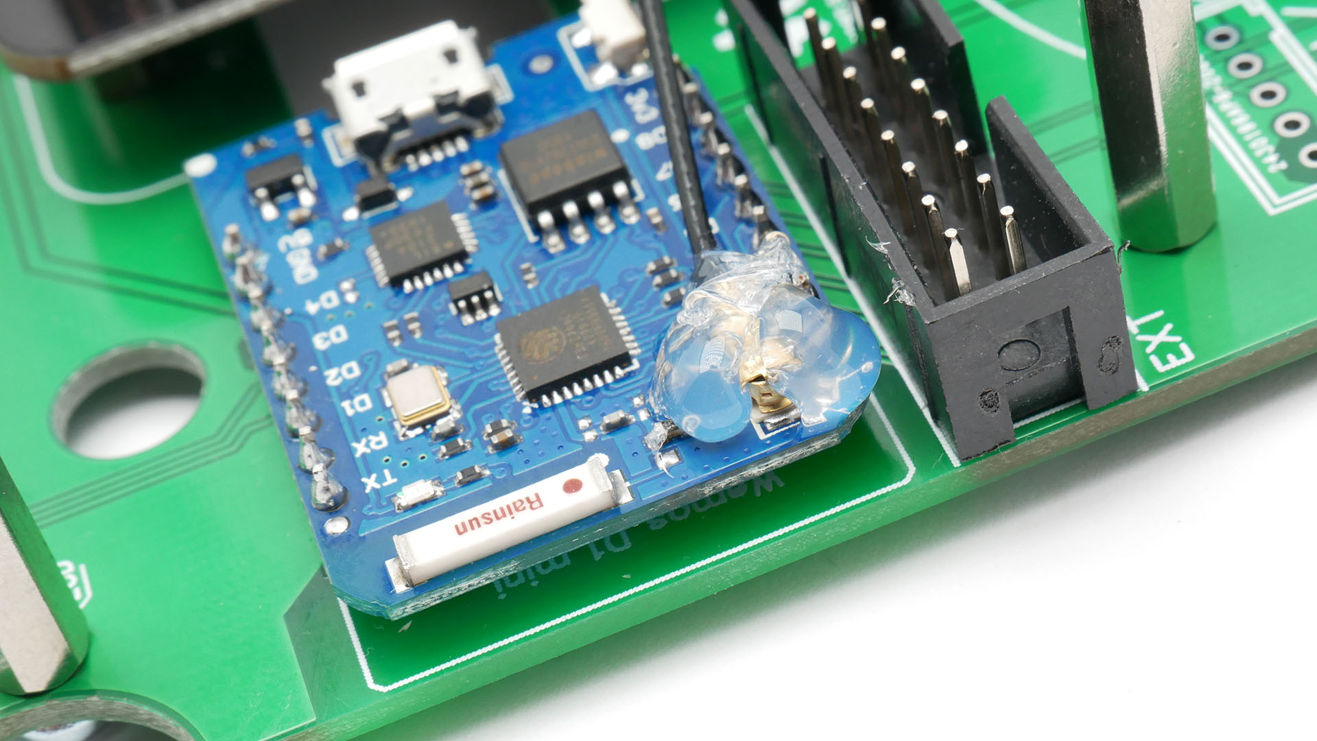
I have attached three pictures
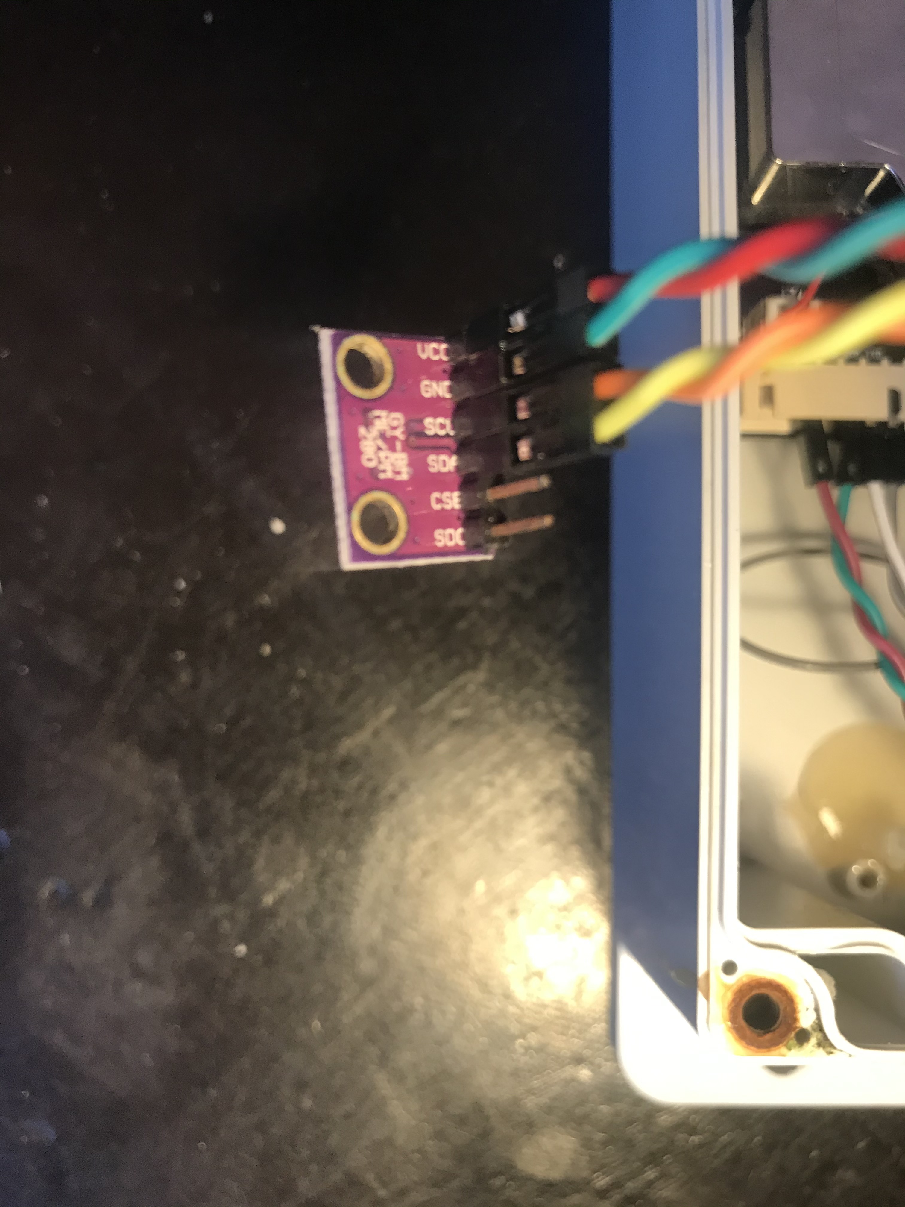
BME280 Wiring
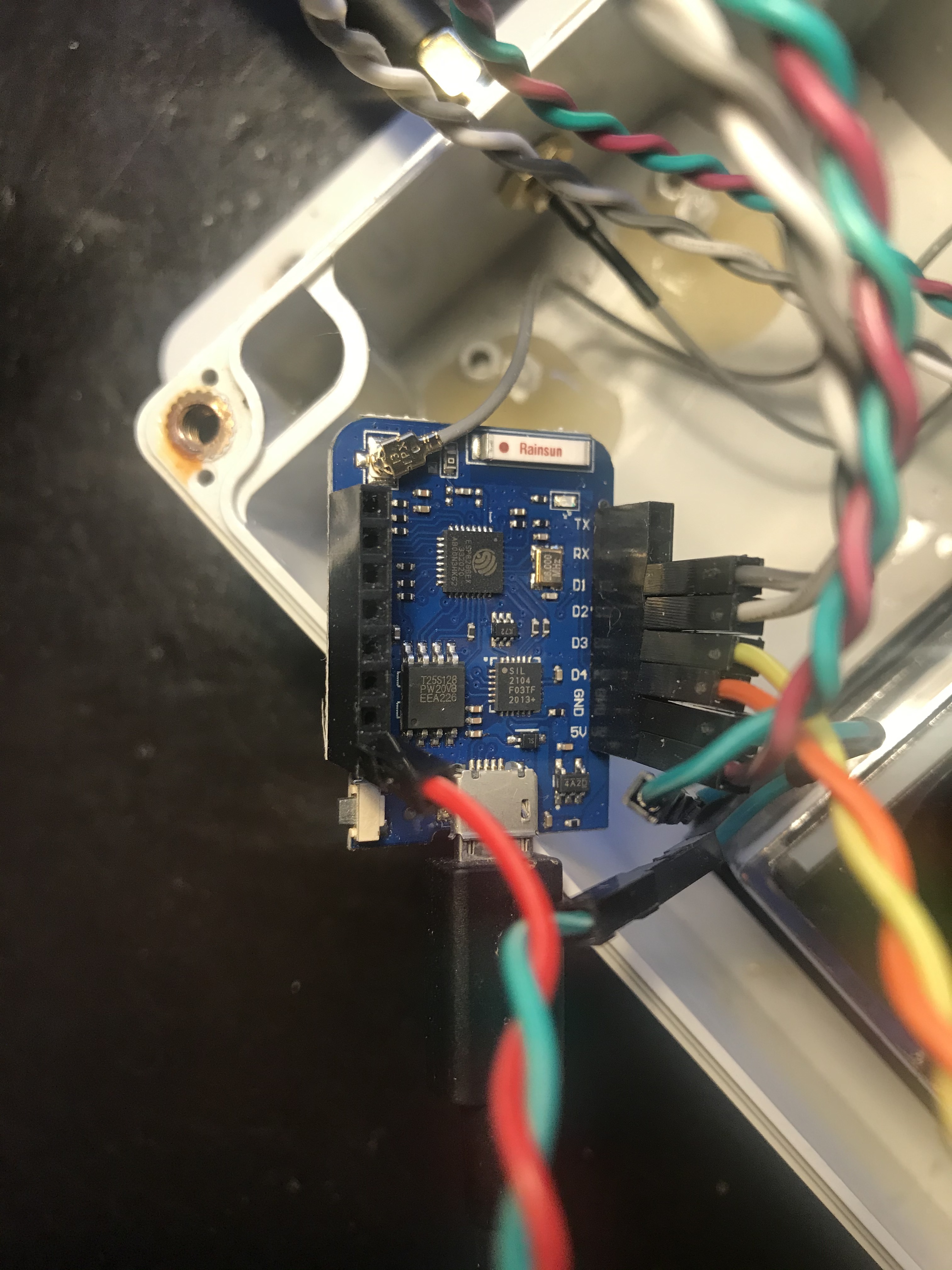
WEMOS DI Pro Mini Wiring
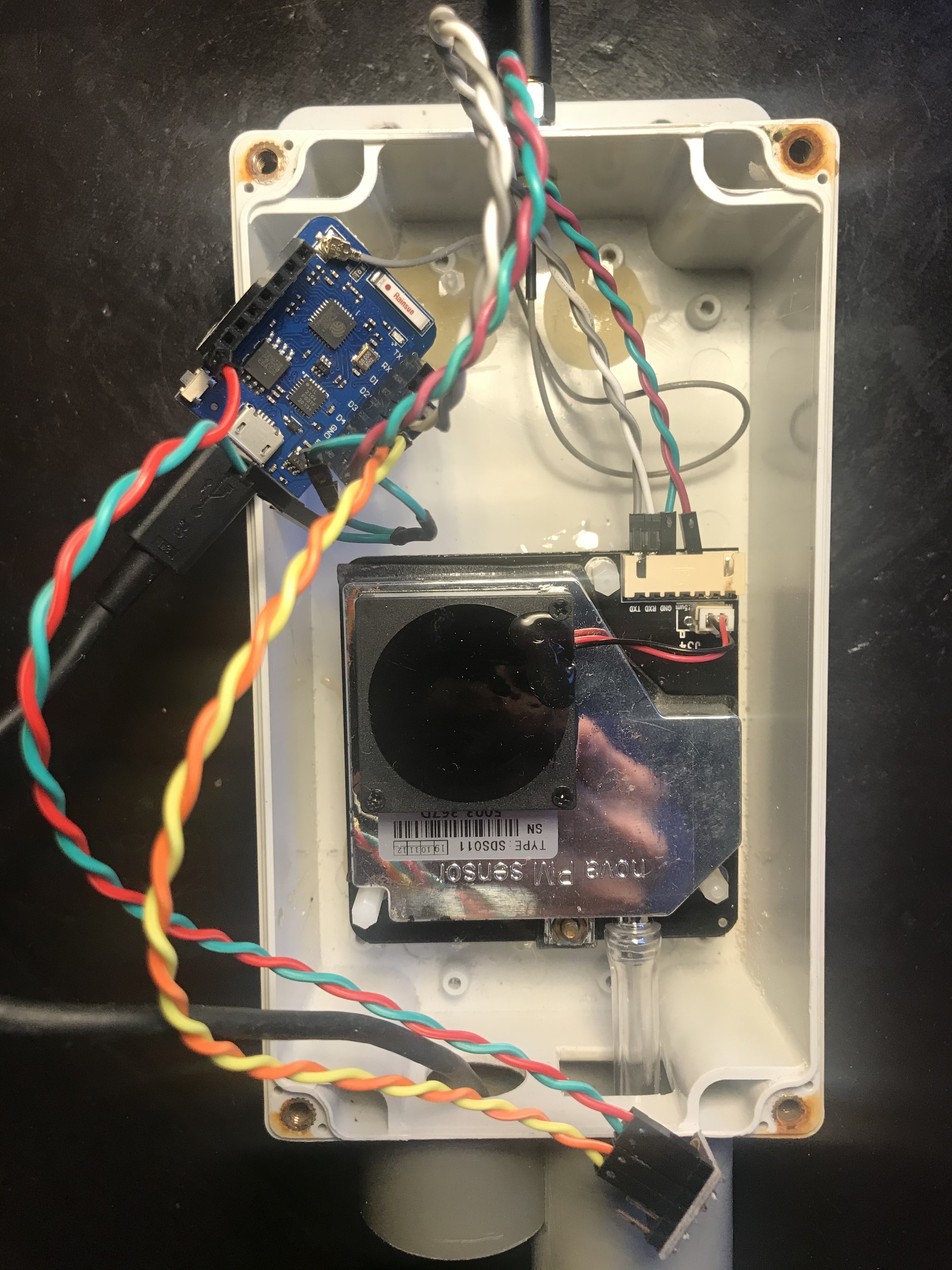
Overall Project Wiring
Can we see the software config ? Send also a screen print to be sure… Always the most trivial first!
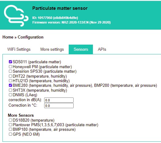
Here is the Config.
I had unplugged it to take the pictures.
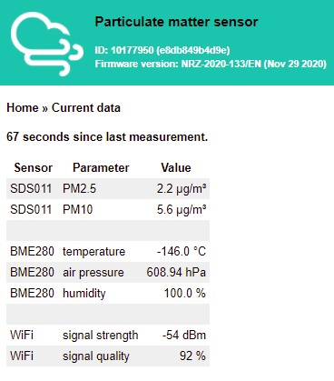
When I restarted it I had bizarre readings from BME280. Yesterday they were simply dash values.
Here are the current values. As you can see the values are meaningless.
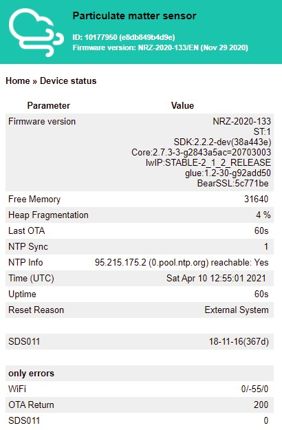
Here is the device Status
I am now more confused…
So I unplugged the bme280 and plugged it back in and rebooted.
Now it thinks its a BMP280.
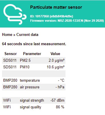
I then did another isolated sensor test and got sensible values for T/P&H so I know its a BME280.
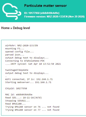
Here’s the Debug
If it becomes a BMP280, it should be an electric problem. It did the same on my sensor when the BME280 oydize. Check the solderings and the pins. Are you 100 % sure of the right connections ? @irukard can you recognize on the pictures ?
Your external antenna is not connected. You are using ceramic one right now. SDS011 position is wrong according to its datasheet.
@pjg
The Sensor works OK on a spare WEMOS D1 Pro Mini which I soldered headers on yesterday purely to test the sensor using the Adafruit test code. What was most interesting is that the BME280 didn’t work on pins D3&D4 but it did work on pins D1&D2 and D5&D7. What are the chances of me preparing two MCU’s both having an electrical problem due to poor soldering? But that was my first thought too, so i resoldered the headers at D3&D4 just to be sure. No improvement. I have done a continuity check on the wiring and it is good.
@irukard
My external antenna is connected physically. What suggests to you that it i not connected?
In what way is the SDS001 position wrong? I have connected the pins as per the instructions
Tx to Pin D1
Rx to Pin D2
5v
Gnd
And it’s working.
Interestingly it doesn’t match the photo using in the assembly instructions. I went by the screen print on the pcb.
Also all the peripheral hardware (SDS011 and BME280) was working just fine with the NodeMCU. I just lacked wifi range. So I literally swaped out the MCU.
I will flash the WEMOS MCU with the Adafruit code to test the BME280 in situ and I will post the results. This will test the wiring and the sensor. I will report back.
Physical antenna is not connected to ESP8266.
You need to change from:
To:
SDS011 - inlet facing down. According to datasheet this position may lead to dust accumulation in measurent chamber.
@irukard
Good spot. I didn’t know that link needed changing. It will be done. Thank you.
The unit sits vertically when positioned outside. It was horizontal on my bench while I sort this problem out.
@pjg
Here are the results of running an I2C scan
On D3 & D4 (airRohr pins) - Nothing detected.
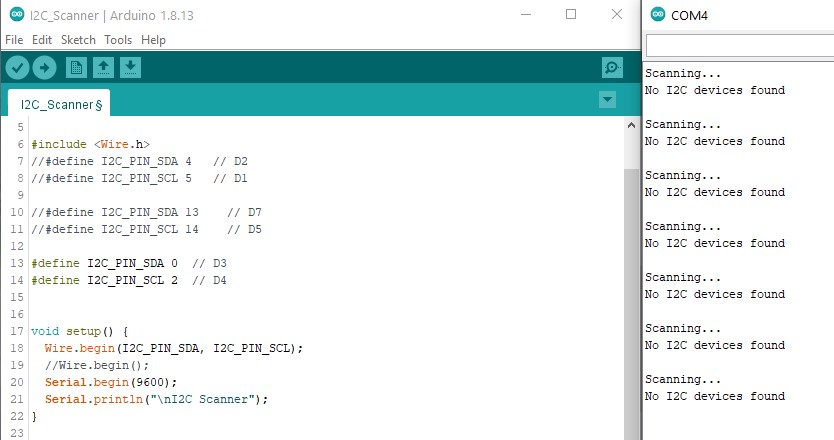
On D5 & D7 - Device detected.

Confirmation its a BME280 and working albeit on D5 & D7.

So, do I have two WEMOS MCU’s that don’t work?
Well, I only have one now as the usb connector broke off one of them…
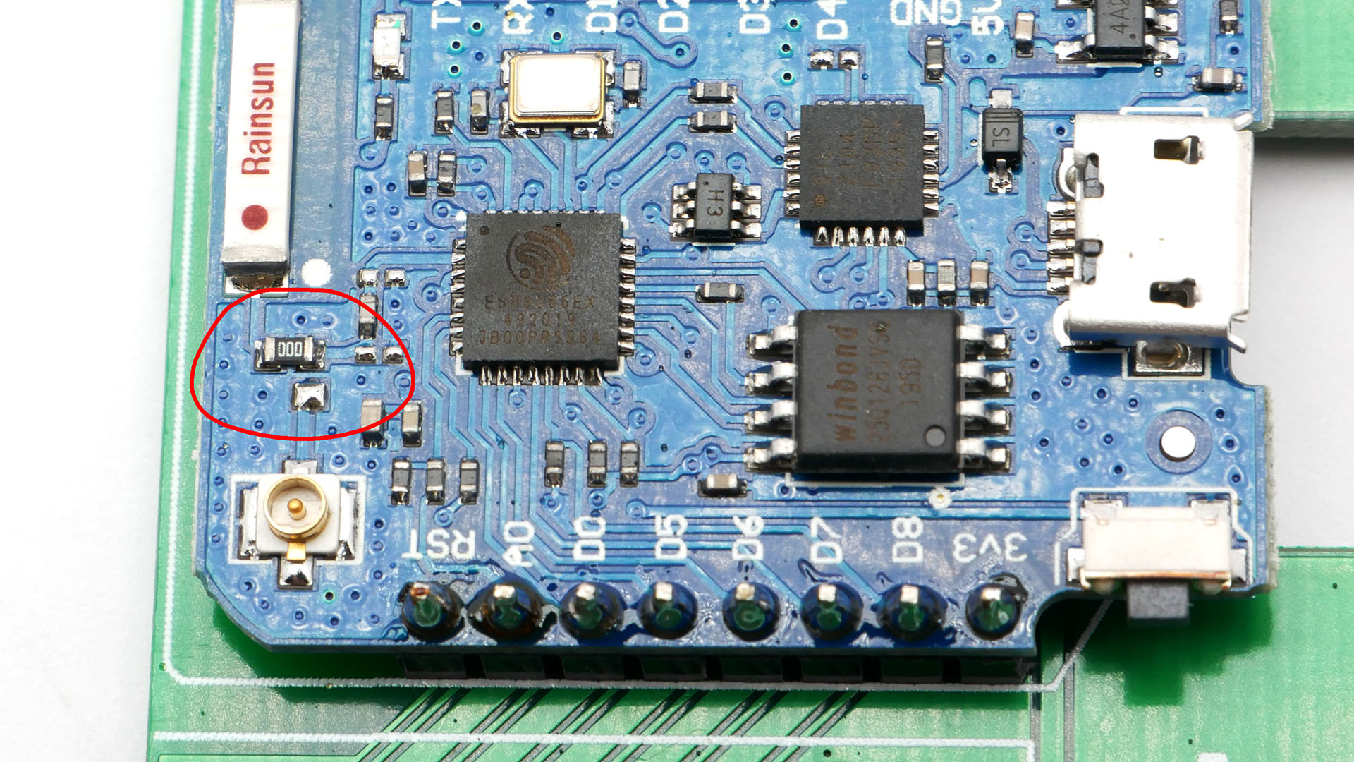
Could you measure pullup resistors on gpio0 and gpio2 on both nodemcu and wemos? May be it’s too small pullup resistance with pullup resistors on bme module?
WEMOS D3(GPIO0)/D4(GPIO2) 12K pullup
BME280 SDA/SCL 10K pullup
NodeMCU D3 / D4 10K pullup
Measured.
Seems better, than nodemcu ![]()
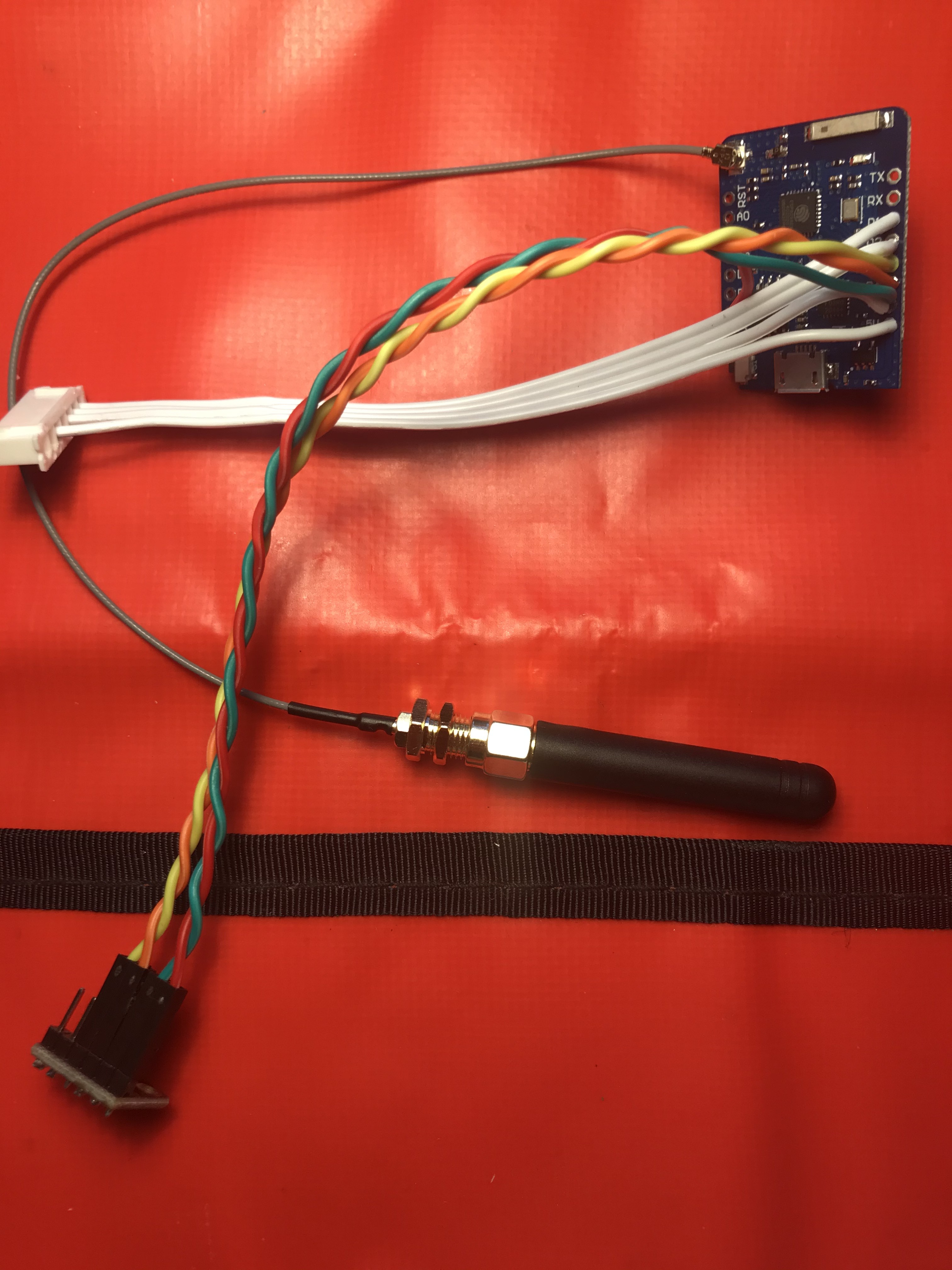
External antenna now working.
Switching that smd resistor is most fiddly.
The signal has improved from -80dBm to -57dBm.
Just a pity I’ve no BME280 data.
I have ordered another WEMOS D1 Pro Mini from another source which should arrive this week. I will hard solder the connections rather than using jumper wires (I’ve also ordered some lead solder as I’m generally struggling with the lead free stuff).
New WEMOS D1 Pro Mini arrived today, from a different supplier.
I converted it to ext. antenna as instructed by @irukard .
I ran a two tests to check the WiFi. It will scan for networks and act as an access point. So the antenna is working.
I hooked up the BME280 to D3 & D4 and it worked OK. Phew…
I assembled everything back into the box.
Note all the wiring is soldered directly to the MCU.

Next I flashed the MCU with the airRohr code, latest_en.bin
No Access Point.
I then reprogrammed the MCU with the test Access Point code from the Arduino IDE and all is good, it produces an AP.
So then I hit ‘Erase Flash’ then reflashed with airRohr firmware.
No Access Point.
I also performed the above with the Old WEMOS that would not read the BME280 and it produces an Access Point etc. So I know my technique is Ok. I just cant get the new WEMOS to produce an Access Point.
Any ideas please?
It is a good idea to secure the antenna cable with hot glue. IPEX connector may short GND to RST pin.
After programming Wemos D1 mini PRO, sometimes you need to manually reset module by pressing button.
Generally in Nettigo we use only one supplier for Wemos D1 mini PRO board. Many previously tested modules was not stable and problematic. I guess it’s all about quality of components and assembly proces.
BTW photos I used to show you antenna jumper and hot glue near antenna connector come from our assembly instruction for NAM 0.3.3 PRO, and are licensed under CC BY-SA 4.0
I tried a manual reset via the button last night. No difference.
What puzzles me is I can code up a working access point on this MCU but the airRohr firmware wont make one. How could this be?
I wondered if I had soldered the antenna link poorly but it shows good continuity when meter checked. Having said that when I code a sketch to scan for wifi networks it finds my neighbours network 60M away and if the antenna was not connected it would not do that.
I know the firmware is OK because with the same release of airRohr firmware the old WEMOS makes an AP. It just does not have I2C.
So I have one WEMOSE with I2C but no AP
and one WEMOS without I2C but will create an AP.
Nightmare.
I will do the hot melt solution when I finally get this working. I thought swapping out MCU’s would be easy,
My mistake was not flashing the WEMOS with airRohr code prior to the antenna mod and subsequent assembly. I was too focused on the I2C issue. Once I had I2C on D3/D4 working on the new WEMOS I thought I was home and dry.
I looked at your Nettigo stuff and I like what you’ve done. Maybe I should just order a WEMOS from Nettigo and know the quality is there. As you say with all the clones out there it can be a challenge. As I have discovered.
I will check the antenna link again.
I will check with another antenna cable in case the connector is a problem.
Anything else with a try?
I have no educated advice but have you tried the latest beta (134 B3)?
I haven’t tried 134 B3
I just select latest_en.bin from the airRohr firmware loader.
How do I select this 134 B3 Beta firmware?
You could enable auto-update and beta firmware in the sensor configuration or get the file from http://firmware.sensor.community/airrohr/beta/