Pretty self explanatory:
NodeMCU 0.9
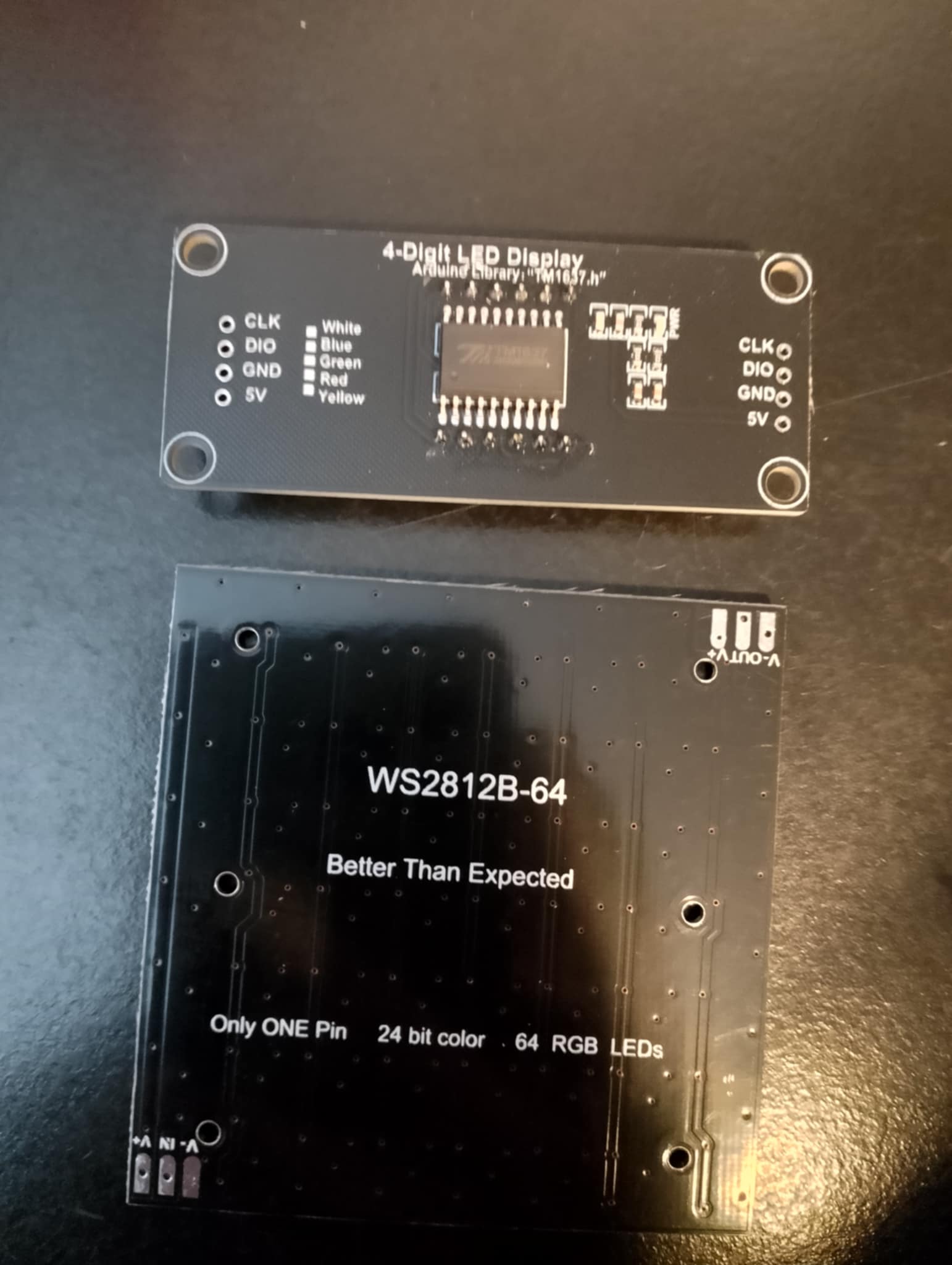
TM1637 4-Digit
WS2812 RGB 8x8
Push button
Who wants further explanations?
Pretty self explanatory:
NodeMCU 0.9
TM1637 4-Digit
WS2812 RGB 8x8
Push button
Who wants further explanations?
keep up the good work!
Compte tenu de mon échec (pour l’instant) avec le moniteur de Nettigo, ton montage m’intéresse beaucoup.
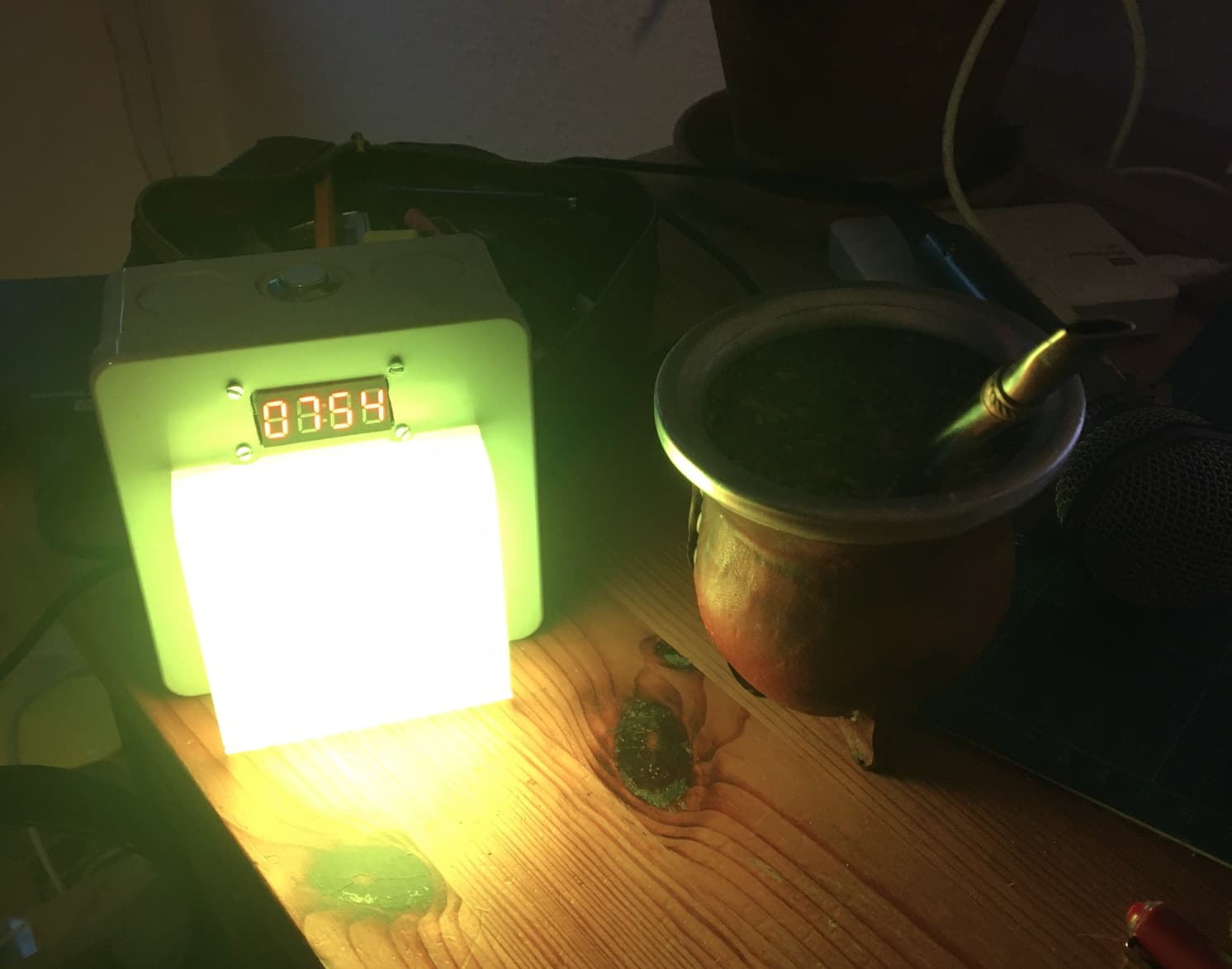
Apparemment il permet de “surveiller” plusieurs capteurs, dommage que la surexposition de ta photo ne montre pas bien de quelle façon la matrice 8x8 affiche.
Merci d’avance pour tes éclaircissements.
Salutations
Neobreton29
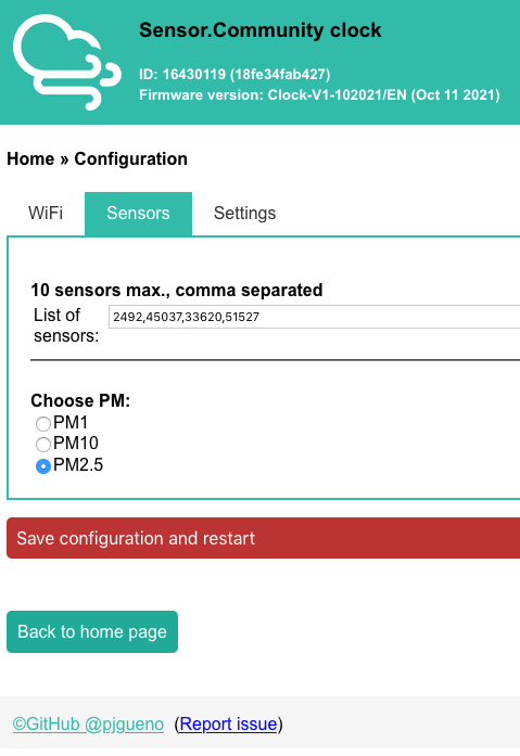
The matrix shows only one colour (it is hidden behind a opalescent acryl plate for better light diffusion): the one of the current sensor. Every 5 min or after a button push, it calls another sensor in the list. After the button push, it shows the sensor ID for a while on the 4 digit screen and comes back to the time. Anyway, it could of course be possible to show 1 sensor pro vertical LED line but in that case the ESP would have to call 8 time the API in a row which could lead to some problems…
You mean this large square below the clock display is the output, and it changes color depending on the particle level? Is it yellow level in the picture?
If so I definitely appreciate the work -but I’ll need some more detail to duplicate it…
Thank you!
H.
Yes! Otherwise you can See the 64 leds. It call the Sensors and reproducteur the RGB Color accordingly to the PM value.
That is very cool! I also have the PM information in a clock I made with a small 5" CRT and a raspberry pi, but it’s much more boring, because it’s only b&w… that’s a mate though?
hello,
i got the parts, time to assemble…
any schematic/photo on how to connect the parts ?
which firmware do you use ?
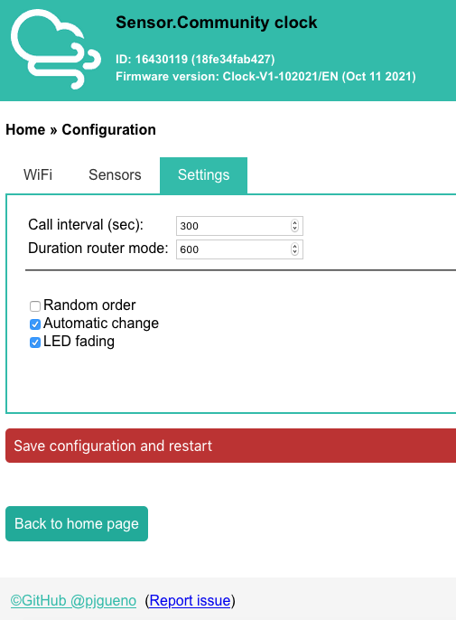
In the code:
#define LED_PIN 2
#define BUTTON_PIN 5
#define CLK 2
#define DIO 3
There should be an issue. I will check in my own clock. But it so old…
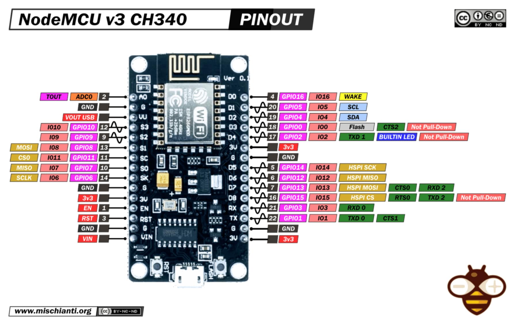
Send me a picture and the pinout of your microcontroller.
So.
Try:
Don’t forget to update the GPIO number in the code.