I use version : , I have 2 sensors SDS011+ BME280 connected, everything works fine, data is sent…
I have an LCD 2004 connected to it, the sensors display well, in the settings of more sensors I saw the option to connect a GPS module (NEO 6M) communication via serial TX RX, when I activate it instead of SDS011, the LCD displays GPS but without any data values…
Does this module “GPS NEO 6M” actually support the firmware? or is it my fault?
The GPS module must be connected to two other pins than the SDS011. The plan was to build a mobile sensor with SDS011 and GPS, but it seemd not possible to use two serial interfaces at the same time…
The pins for GPS are defined as following: #define GPS_SERIAL_RX D5 #define GPS_SERIAL_TX D6
ok, when I have the NEO-M8M module I will connect it and write how…
another question, is it possible to connect the SDS011 + SPS30 sensors to one ESP8266 module at the same time? I guess they use the same RX/TX pin
I would like to compare measurements…
in general, is there a list of connected pins somewhere and all supported sensors in the FW? I don’t have the code from which I would read it…
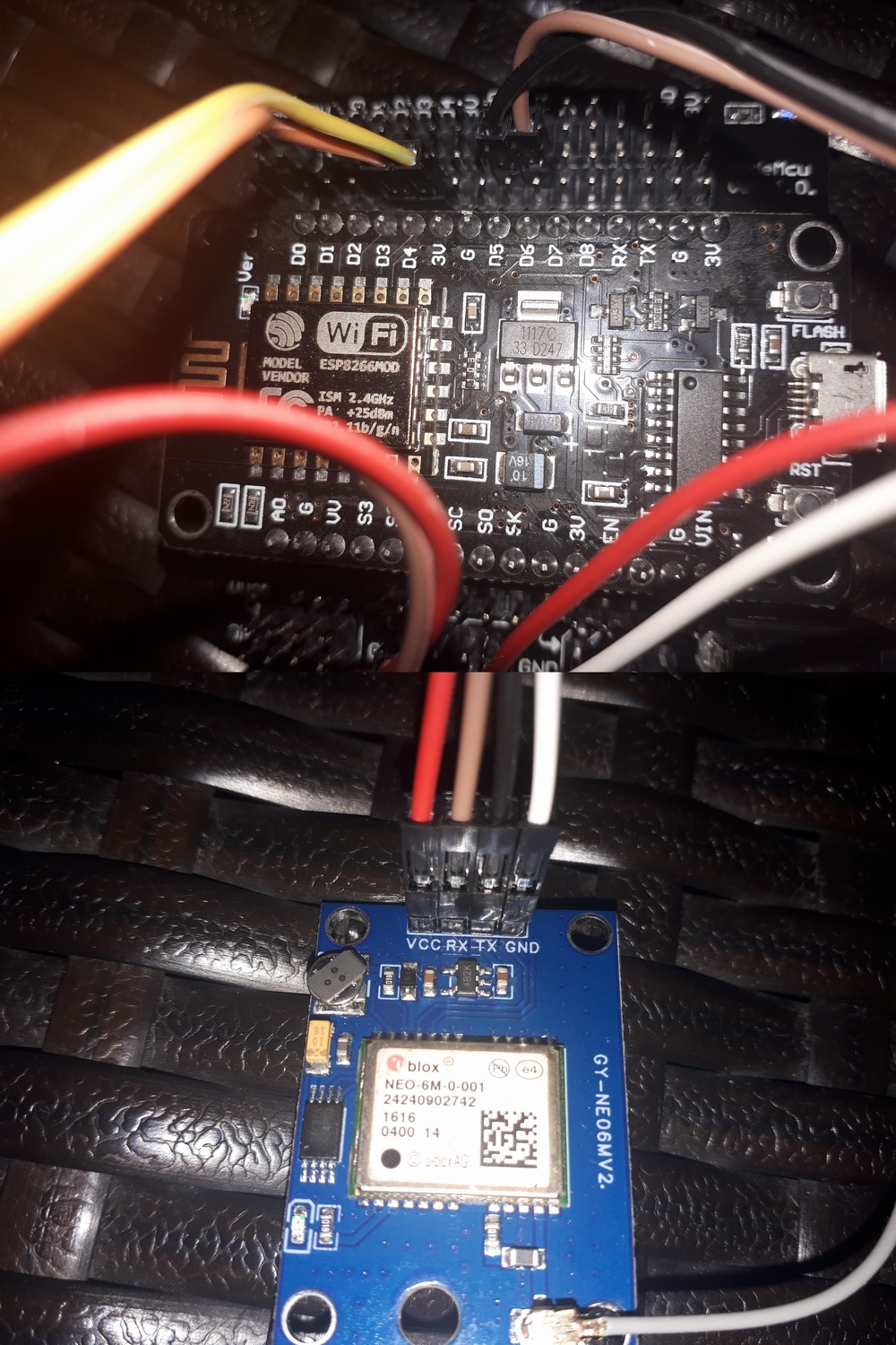
GPS NEO 6M (serial) !!! USE AT OWN RISK, in combination with PM sensor the firmware may crash !!!
VCC and GND can be provided by board (use 3.3v!)
Note: Serial connections are always crossed (RX on one side is connected with TX on other side)
TX von Neo → Pin D5 (RX)
RX von Neo → Pin D6 (TX)
Sensor.Community API “Pins”
For use of multiple sensors with Sensor.Community, you need to specify a virtual API Pin in the sensor registration form at devices.sensor.community. The firmware uses the following API pins hardcoded. These match what the Sensor.Community API expect and will be used by default when selecting the correct sensor model.
HPM/PMS/SDS011/SPS30 => Pin 1
BME280 => Pin 11
BMP180/BMP280 => Pin 3
DHT22/HTU21D/SHT3x => Pin 7
GPS(Neo-6M) => Pin 9
DS18B20 => Pin 13
DNMS +> Pin 15
a few exotic sensors in the beta version like the Next PM, the SEN5Xs, IPS-7100…
yes, SPS30 uses UART or I2C connection…
sorry I thought it was connected as SDS011 on TX/RX, that’s why I had a question about the connection…
thanks for the detailed description of connecting the sensors to the programmed pins…
one more question regarding displaying data on LCD 2004,
we have 4 lines and 20 characters available,
when the sensor sends 4 lines of data + 1 line is taken by the sensor name from FW, not everything is displayed on the LCD, can it be fixed? or is it necessary to edit the FW? or use another LCD?
e.g. something similar where I can turn on or off WiFi and device info in the LCD settings.