Is it possible to display sensor data on a screen attached to the microcontroller?
In Poland we got standalone solution with touch screen and Wemos D1 mini.
Hardware: WiFi Enabled 2.4" Touch Screen with SD Reader - EasyEDA
Software: GitHub - trekawek/aqi-lcd
It may fetch data.json directly from sensor via WiFi (inside one LAN) or via Internet - for example from aqi.eco service.
If you want to buy it at Nettigo:
- PCB: Nettigo: PCB for WiFi Enabled 2.4" Touch Screen with SD Card Reader
- KIT: Nettigo: LCD 2.4" with touch for Wemos D1 Mini - soldering kit (English product description is literally non existent)
It’s Open Hardware licensed under TAPR. Feel free to fork it and modify 
1 Like
Thanks. Actually, I was asked by one of the community member who is hosting these sensors in Greece to help add the TFT display to the sensor. As I have gone through the github repo, I couldn’t see Arduino files there. It seems the Python flasher is burning the ino files on the nodemcu. If I could have access to that code, I can add the display module code inside as well for those who wish to have display on the sensor. That was the idea.
Oh. You want to add TFT Display to ESP8266 with SDS011 and BME280. I am afraid you may have problem with that. Most of TFT displays runs via SPI, and some of SPI ports are already occupied by other things like GPS/CO2 sensors, DS18B20, etc. Also you will quickly run off memory.
Right now your only easy option is to add display via I²C. Character display with PCF8574 converter, OLED based on SSD1306 and similar solutions.
AirRohr firmware use PlatformIO. Code is written in Arduino compatible form - mostly in C++.
Python is used on some stage by PlatformIO itself. ino/cpp files are compiled to binary form and than flashed on SPI Flash chip inside ESP-12 module. ESP8266 boots from external SPI flash.
1 Like
Thanks. Will go through the code. Will also check with the member how many sensors he is using with the controller to see if there are available serial interface for the display.
This is what we have:
TX (/IO1) (boot failure if pulled low / high on boot)
RX (IO3) (high on boot)
D0 (IO16) - not used (high on boot)
D1 (IO5) - SDS011 TX
D2 (IO4) - SDS011 RX
D3 (IO2) - I2C SDA (pulled high / boot failure if pulled low / high on boot)
D4 (IO0) - I2C SCL (pulled high / boot failure if pulled low)
D5 (IO14) - HW SPI CLK - Used as UART RX for GPS/CO2 Sensors
D6 (IO12) - HW SPI MISO - Used as UART TX for GPS/CO2 Sensors
D7 (IO13) - HW SPI MOSI - Used for OneWire/DHT22
D8 (IO15) - (pulled low / boot failure if pulled high)
And standard SPI 2.4" TFT (TJCTM24024-SPI) requires minimum: 6 pins
So if you don’t use OneWire, DHT22, GPS it may be technically possible… But this D0 as LCD D/C may not work.
LCD CS (D8)
LCD RESET (ESP RESET)
LCD D/C (maybe, just maybe D0)
LCD MOSI (D7)
LCD SCK (D5)
LCD MISO (D6)
The firmware supports some display type. Just check the settings page. For most use cases the LCD displays should be good enough.
And there is only limited RAM and flash memory for the firmware. So do we really need to include code for a use case that is needed only by a “handful” of users? Or isn’t the splitted solution a better idea?
There is of course possibility od adding additional µc in I²C slave mode to drive LCD according to received simple instructions from ESP8266. I did something like that with WS2812b LED bar and Attiny84 as I²C slave.
From ESP8266 point of view this form of communication is actually very memory efficient. You don’t need additional libraries (since Wire for I²C is already used in project). And sending commands is really simple:
void lightLED(byte mode, byte cnt, byte red, byte green, byte blue) {
Wire.beginTransmission(0x32);
Wire.write(mode);
Wire.write(cnt);
Wire.write(red);
Wire.write(green);
Wire.write(blue);
Wire.endTransmission();
}
However it requires a little more hardware than direct connection. And code in this intermediary µc is not very easy to update. Maybe UPDI 1-pin programming for ATtiny3217 and similar µc might be a valid solution for the future. That would open door for custom sensors connected via I²C, with individual calibration, serial numbers, work time measurement, aging management, etc. This idea bounces in my head for more than a year.
Great. Will test it out. Thanks for the explanation.
But why connecting a controller (for around 5 bucks) with I2C when you can use a second ESP3266 for around 3 bucks) to access the data via wifi?
That’s fair point. Ease of installation maybe? No need for additional power source?. I explore many hardware possibilities, to know the limitations of each technology. DNMS also works as I²C slave device. And this is also a good method for interfacing wind speed and direction sensors.
And another case where to split the parts. Wind directions shouldn’t be measured near buildings or streets (or high enough that this is not a problem), while the PM measurement should be on “heads height” and mostly near a building. So you shouldn’t use the same location for these.
I can use Stevenson’s Cage in my garden
Hello irukard,
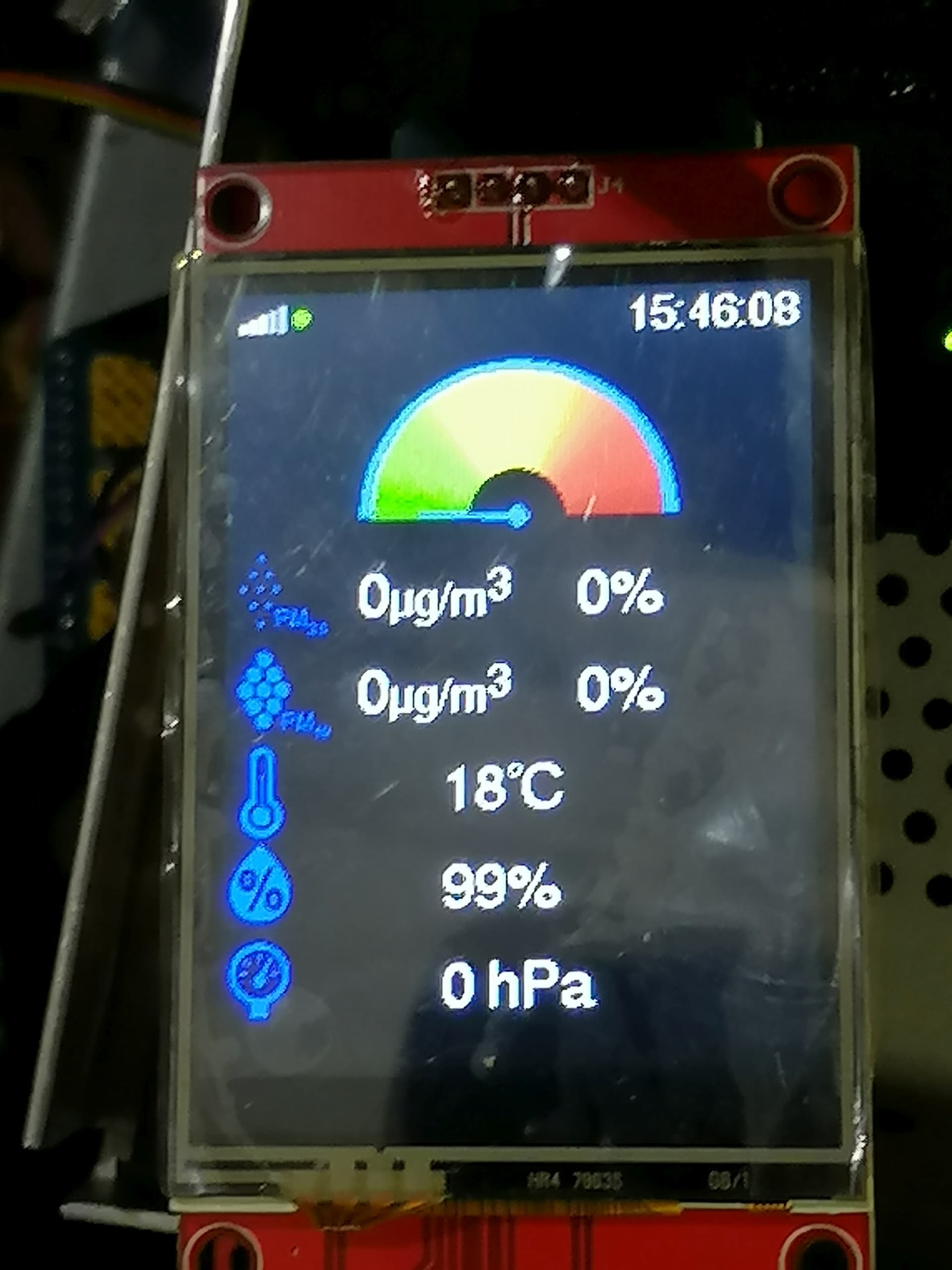
I just bought the 1979 Nettigo kit, in order to follow my SC sensors.
As soon as I received it, as soon as I assembled and programmed it, I was very disappointed…
A nice display but no data.
What are the settings to collect data from my sensors?
They send their data to :
Sensor.Community
Madavie.de
Feinstaub-App
Aircms.online
OpenSenseMap.org
I am in France, and I am creating an air quality observation network in my region.
Thank you for your attention
Neobreton29
Hi,
Can you put the link to the “1979 Nettigo Kit”, I can’t find it.
Do you really need to send to these systems ?
- Feinstaub-App
- Aircms.online
- OpenSenseMap
Did you have accounts for them ?
Bonjour,
https://air.nettigo.pl/baza-wiedzy/wyswietlacz-z-wifi-firmware/
Since my message, I tried to register one of my SC sensors on the NAM site, but it doesn’t seem to work ???
The firmware for this device is only reading the JSON of a sensor in the same network than this device. For other data you need to modify this firmware.
Maybe you could ask the developers of this firmware to extend it to read the values from one of our API “endpoints”.
OK, thank you very much.
Hello,
A little more information.
Some mail exchanges with Witold Rugowski, from Nettigo, allowed me to load on the display module a firmware which makes it visualize the data of a station (SC of origin) on the local network (wifi). There is even a fix for using a DHT22 and its erroneous TH measurements.
1 Like
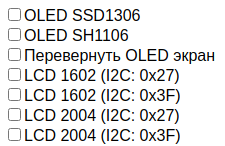
Hello, I recently assembled a sensor and there are items in the firmware settings (in the picture).
I have not found on the Internet how to connect the display to the sensor, please share a link or information on how to connect the displays correctly and which menu items to choose depending on the display