# Circuit diagram of SDS011 PM sensor
**URL:** https://forum.sensor.community/t/circuit-diagram-of-sds011-pm-sensor/145
**Category:** Uncategorized
**Created:** [December 29, 2020, 7:35pm UTC](https://forum.sensor.community/t/circuit-diagram-of-sds011-pm-sensor/145 "2020-12-29T19:35:50Z")
**Posts on this page:** 20
**Page:** 1
### Author:  [@Denis](https://forum.sensor.community/u/Denis)
#### Post date: [December 29, 2020, 7:35pm UTC](https://forum.sensor.community/t/circuit-diagram-of-sds011-pm-sensor/145/1 "2020-12-29T19:35:50Z")
Is there a circuit diagram available for the SDS011 sensor like the one for PPDns given [here](https://github.com/opendata-stuttgart/meta/blob/master/files/ShinyeiPPD42NS_Deconstruction_TracyAllen.pdf)?
I have a number of broken SDS011. Some of them are known to be broken by reversing + and -. Maybe it is possible to fix them easily?
---
### Author:  [@TBallam](https://forum.sensor.community/u/TBallam)
#### Post date: [January 1, 2021, 10:42am UTC](https://forum.sensor.community/t/circuit-diagram-of-sds011-pm-sensor/145/2 "2021-01-01T10:42:39Z")
Haven’t found a schematic but the MCU appears to be a STM32F038K6 so power might not be connected directly to the MCU,
Have to take down a sensor today so will have a look at the power supply side of things if I get a chance.
---
### Author:  [@Denis](https://forum.sensor.community/u/Denis)
#### Post date: [January 1, 2021, 10:46am UTC](https://forum.sensor.community/t/circuit-diagram-of-sds011-pm-sensor/145/3 "2021-01-01T10:46:30Z")
Found this interesting information with some internals:
[https://revspace.nl/DustSensor](https://revspace.nl/DustSensor)
---
### Author:  [@TBallam](https://forum.sensor.community/u/TBallam)
#### Post date: [January 1, 2021, 11:15am UTC](https://forum.sensor.community/t/circuit-diagram-of-sds011-pm-sensor/145/4 "2021-01-01T11:15:10Z")
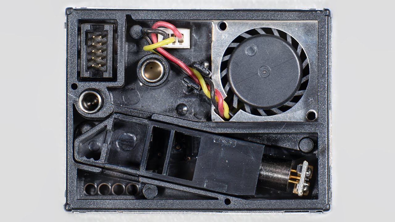
This is for the plant power device but it gives an idea, it’s probably the power regulation that’s blown as he said he’s repaired one by replacing a low dropout regulator.
[ ](https://www.youtube.com/watch?v=QgO0iWpK7Ho)
---
### Author:  [@TBallam](https://forum.sensor.community/u/TBallam)
#### Post date: [January 1, 2021, 11:58am UTC](https://forum.sensor.community/t/circuit-diagram-of-sds011-pm-sensor/145/5 "2021-01-01T11:58:05Z")
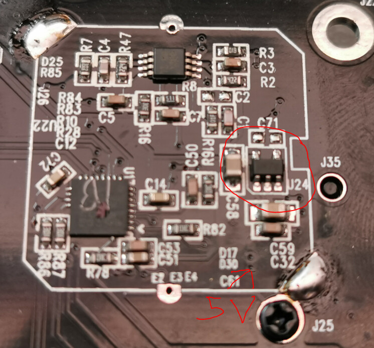
U24 marked DK7y is a LDO and probably what has given out the magic smoke.
---
### Author:  [@TBallam](https://forum.sensor.community/u/TBallam)
#### Post date: [January 1, 2021, 12:06pm UTC](https://forum.sensor.community/t/circuit-diagram-of-sds011-pm-sensor/145/6 "2021-01-01T12:06:42Z")
You might want to replace the 5V6 zener diode and the 68uF capacitor at these locations too
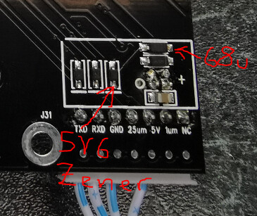 When one of my SDS011s or someone can supply a dead SDS011m I’ll have a go at doing a full reverse engineering.
---
### Author:  [@irukard](https://forum.sensor.community/u/irukard)
#### Post date: [March 2, 2021, 4:03pm UTC](https://forum.sensor.community/t/circuit-diagram-of-sds011-pm-sensor/145/7 "2021-03-02T16:03:39Z")
> [@TBallam](#):
>
> the 68uF capacitor
I don’t think this is a capacitor 🙂
If I am not mistaken D17 is a Schottky diode in SOD-123 package. Marked as SL {YM}. Part number probably 1N5819HW.
Directly below you will have D30 Zener diode in SOD-123 package. Marked as W8 so it may be BZT52-C5V1.
Than J34 - fan terminal.
C61 - 20µF capacitor
And E2, E3 and E4 in fact may be UDZ5V6B Zener diodes in SOD-323 package. Marked as W8. Exactly as you described.
U24 - marked as DK 8P - LDO in SOT25 package.
Probably AP131-25W
---
### Author:  [@irukard](https://forum.sensor.community/u/irukard)
#### Post date: [March 3, 2021, 11:17am UTC](https://forum.sensor.community/t/circuit-diagram-of-sds011-pm-sensor/145/8 "2021-03-03T11:17:18Z")
There are two components I have problem with identifying:
R4 - Photo Sensor with size 4,5 x 4mm
Marking on botom 7C 23.
U1 - Transimpedance amplifier (TIA)
8-pin, 3x3mm
Makings on top: TI 13F6
On bottom: 87A P2XR
| Designation | Type | Package | Marking | Part number | Value | Remarks |
| --- | --- | --- | --- | --- | --- | --- |
| R4 | Photo Sensor | 4,5 x 4mm | From bottom 7C 23 | | | |
| C1 | Capacitor | 0603 | | | | |
| C2 | Capacitor | 0603 | Not populated | | | |
| C3 | Capacitor | 0603 | | | | |
| C4 | Capacitor | 0603 | | | | |
| C5 | Capacitor | 0603 | | | | |
| C7 | Capacitor | 0603 | | | | |
| C12 | Capacitor | 0603 | | | | |
| C14 | Capacitor | 0603 | | | | |
| C32 | Capacitor | 0603 | | | | |
| C50 | Capacitor | 0603 | | | | |
| C51 | Capacitor | 0603 | | | | |
| C53 | Capacitor | 0603 | | | | |
| C58 | Capacitor | 0805 | | | | |
| C59 | Capacitor | 0805 | | | | |
| C61 | Capacitor | 0603 | | | 20µF | |
| C71 | Capacitor | 0603 | Not populated | | | |
| C72 | Capacitor | 0603 | | | | |
| D17 | Schottky diode | SOD-123 | SL {YM} | 1N5819HW | | |
| D25 | LED | 0805 | | | | Red LED |
| D30 | Zener diode | SOD-123 | W8 | BZT52-C5V1 | | |
| E2 | Zener diode | SOD-323 | BC | UDZ5V6B | | |
| E3 | Zener diode | SOD-323 | BC | UDZ5V6B | | |
| E4 | Zener diode | SOD-323 | BC | UDZ5V6B | | |
| J26 | Terminal | | | | | Laser terminal |
| J31 | Terminal | XH-2.54-7P | | | | UART interface |
| J34 | Terminal | | | | | Fan terminal |
| R1 | Resisor | 0603 | 01F | | 10MΩ 1% | |
| R2 | Resisor | 0603 | 472 | | 4,7kΩ | |
| R3 | Resisor | 0603 | 01B | | 1kΩ 1% | |
| R7 | Resistor | 0603 | 302 | | 3kΩ | |
| R8 | Resisor | 0603 | 511 | | 510Ω | |
| R9 | Resisor | 0603 | 01C | | 10kΩ 1% | |
| R10 | Resistor | 0603 | 30X | | 20Ω 1% | |
| R16 | Resisor | 0603 | 30E | | 2MΩ 1% | |
| R28 | Resistor | 0603 | 01D | | 100kΩ 1% | |
| R47 | Resistor | 0603 | 224 | | 220kΩ | |
| R78 | Resisor | 0603 | 01C | | 10kΩ 1% | |
| R82 | Resisor | 0603 | 01C | | 10kΩ 1% | |
| R83 | Resistor | 0603 | 30X | | 20Ω 1% | |
| R84 | Resistor | 0603 | 01D | | 100kΩ 1% | |
| R85 | Resistor | 0603 | 512 | | 5,1kΩ | |
| R86 | Resisor | 0603 | 30X | | 20Ω 1% | |
| R87 | Resisor | 0603 | 30X | | 20Ω 1% | |
| U1 | TIA | 8-pin 3x3mm | Top: TI 87 13F6 / Bottom: 87A P2XR | | | Transimpedance amplifier (TIA) |
| U17 | MCU | UFQFPN32 5x5mm | F031K6 | STM32F031K6 | | Main MCU |
| U22 | Transistor | TSOP-6 | HOYA 14 | AO6800 | | MOSFET |
| U24 | LDO | SOT25 | DK 8P | AP131-25W | | |
---
### Author:  [@irukard](https://forum.sensor.community/u/irukard)
#### Post date: [March 4, 2021, 11:31am UTC](https://forum.sensor.community/t/circuit-diagram-of-sds011-pm-sensor/145/9 "2021-03-04T11:31:08Z")
Here is some work in progress: [NovaFitness SDS011 V2.18 Reverse Engineering – Google Drive](https://drive.google.com/drive/folders/1dYfTKWfNPUzSq2Vn_G9QBCdwv0EURTDX)
You will find there BOM, IC datasheets, photos and additional resources.
I would like to measure exact values of all capacitors and identify all components. Than I will draw schematics in EasyEDA, and design prototype PCB. I will add some new features to this board - like ability to flash own firmware.
With deep understanding of construction and proper schematics repairing broken SDS011 should be easy. Also we could experiment with improving this device. And maybe in future NovaFitness would like to talk with us - right now (despite of selling thousands of theirs sensors) they treat us like idiots. Which is unfortunate.
---
### Author:  [@Denis](https://forum.sensor.community/u/Denis)
#### Post date: [March 4, 2021, 8:00pm UTC](https://forum.sensor.community/t/circuit-diagram-of-sds011-pm-sensor/145/10 "2021-03-04T20:00:37Z")
There is one guy in our local community who is doing quite the same work. Forwarded information to him. Hope he will manage to register on the forum and add something valuable.
---
### Author:  [@irukard](https://forum.sensor.community/u/irukard)
#### Post date: [March 5, 2021, 3:31pm UTC](https://forum.sensor.community/t/circuit-diagram-of-sds011-pm-sensor/145/11 "2021-03-05T15:31:10Z")
U1 seems to be TLV2376IDG in VSSOP (8) package
Got two units marked as: TI 87 13F6, TI 01 13F6
13F6 is the same across different years.
---
### Author:  [@Mogwaika](https://forum.sensor.community/u/Mogwaika)
#### Post date: [March 5, 2021, 7:12pm UTC](https://forum.sensor.community/t/circuit-diagram-of-sds011-pm-sensor/145/12 "2021-03-05T19:12:34Z")
I tried to reverse old one. In that device V2-008 they use OA TI OPA2376 and LDO TX6211B.
TLV2376 seems almost same characteristics.
Also draw some schematic in EasyEDA for it and measure signals after first stage TIA and second stage amplifier, there are very noisy with 100 mV needles with 5 ms period, I think because they didn’t use rc-filter and signal buffer before STM’s ADC.
---
### Author:  [@Denis](https://forum.sensor.community/u/Denis)
#### Post date: [March 6, 2021, 11:47am UTC](https://forum.sensor.community/t/circuit-diagram-of-sds011-pm-sensor/145/13 "2021-03-06T11:47:51Z")
I wounder is it possible to load new firmware to STM processor over standard connection of SDS? Or it must be done via connector pad located on the PCB?
---
### Author:  [@Denis](https://forum.sensor.community/u/Denis)
#### Post date: [March 6, 2021, 11:51am UTC](https://forum.sensor.community/t/circuit-diagram-of-sds011-pm-sensor/145/14 "2021-03-06T11:51:42Z")
The biggest drawback of the closed source FW is that you don’t know how it works. If the measurements are raw one or some sort of a math model… If it could be “opened” then there will be more information…
---
### Author:  [@Mogwaika](https://forum.sensor.community/u/Mogwaika)
#### Post date: [March 6, 2021, 12:12pm UTC](https://forum.sensor.community/t/circuit-diagram-of-sds011-pm-sensor/145/15 "2021-03-06T12:12:49Z")
Yes. I think “rx”, “tx” and “nc” as boot0 are enough for it.
---
### Author:  [@irukard](https://forum.sensor.community/u/irukard)
#### Post date: [March 7, 2021, 3:19pm UTC](https://forum.sensor.community/t/circuit-diagram-of-sds011-pm-sensor/145/16 "2021-03-07T15:19:31Z")
> [@Mogwaika](#):
>
> Yes. I think “rx”, “tx” and “nc” as boot0 are enough for it.
Indeed. It might be possible.
> [@Mogwaika](#):
>
> Also draw some schematic in EasyEDA
This is exactly what I want to do. I will also replicate PCB to make a open source version with experiments in mind.
I’ve just measured values of capacitors.
| Designation | Package | Value | Measured value |
| --- | --- | --- | --- |
| C1 | 0603 | ??? | ??? |
| C2 | 0603 | — | — |
| C3 | 0603 | 100nF | 120nF |
| C4 | 0603 | 10nF | 9nF |
| C5 | 0603 | 100nF | 120nF |
| C7 | 0603 | 100nF | 120nF |
| C12 | 0603 | 100nF | 120nF |
| C14 | 0603 | 10µF | 8,7µF |
| C32 | 0603 | 100nF | 120nF |
| C50 | 0603 | 100nF | 120nF |
| C51 | 0603 | 4,7µF | 4,53µF |
| C53 | 0603 | 100nF | 120nF |
| C58 | 0805 | 20µF | 20µF |
| C59 | 0805 | 20µF | 20µF |
| C61 | 0805 | 20µF | 20µF |
| C71 | 0603 | — | — |
| C72 | 0603 | 10µF | 8,6µF |
I didn’t got any readings on C1 capacitor.
---
### Author:  [@Mogwaika](https://forum.sensor.community/u/Mogwaika)
#### Post date: [March 7, 2021, 6:08pm UTC](https://forum.sensor.community/t/circuit-diagram-of-sds011-pm-sensor/145/17 "2021-03-07T18:08:05Z")
I think capacitor in feedback of this TIA will be 100-1000 pF, 300 pF most plausible.
I’ll try to desolder and measure.
Do you want make a better one sensor or fully compatible board?
---
### Author:  [@irukard](https://forum.sensor.community/u/irukard)
#### Post date: [March 8, 2021, 12:43pm UTC](https://forum.sensor.community/t/circuit-diagram-of-sds011-pm-sensor/145/18 "2021-03-08T12:43:11Z")
> [@Mogwaika](#):
>
> Do you want make a better one sensor or fully compatible board?
We will see 🙂 I always want to push designs to it’s limits. Understanding design is one thing, improving another. I would like to try write own firmware for SDS011.
STM32 power rail runs on 3.3V. LDO TX6211B and AP131-25W have similar package markings, but I don’t think we found exact LDO used in SDS011.
“DK” in case of TXSemi TX6211B means 3.0V variant [link](http://www.txsemi.com/Upload/TX6211B_V12-11264794020.pdf)
“DK” on AP131 means 2.5V variant
So I don’t think we know exact part number and manufacturer of this LDO.
---
### Author:  [@Mogwaika](https://forum.sensor.community/u/Mogwaika)
#### Post date: [March 8, 2021, 2:05pm UTC](https://forum.sensor.community/t/circuit-diagram-of-sds011-pm-sensor/145/19 "2021-03-08T14:05:26Z")
In my device there are 3.3V “DE=A1D”, and I think this part is not very important.
Most important to understand is there any calculations with amplitude of impulses or stupid counting impulses above some level at first and second stages of amplifier and produce pm10 and pm2.5 respectively.
But stm could work from 2.0 to 3.6 volts, OpAmp too, main question is laser and how it works from different voltages.
---
### Author:  [@irukard](https://forum.sensor.community/u/irukard)
#### Post date: [March 8, 2021, 2:19pm UTC](https://forum.sensor.community/t/circuit-diagram-of-sds011-pm-sensor/145/20 "2021-03-08T14:19:51Z")
> [@Mogwaika](#):
>
> In my device there are 3.3V “DE=A1D”
Perfect! I will put TX6211B in schematics. I think I will read a datasheet to be sure that this part is not very important and may be swapped for another with similar characteristics.
> [@Mogwaika](#):
>
> Most important to understand is there any calculations with amplitude of impulses or stupid counting impulses above some level at first and second stages of amplifier and produce pm10 and pm2.5 respectively.
So basically it looks like poor and noisy design which works only because of proper calibration.
[Next page](https://forum.sensor.community/t/circuit-diagram-of-sds011-pm-sensor/145.md?page=2)